- Aerosols are small particles of liquids or solids suspended in a carrying gas
- Medical aerosols can be produced by a nebulizer
- The therapeutic efficacy of the aerosol is dependent on the liquid or solid’s ability to remain in suspension and the depth reached by the aerosol on inhalation, and is dependent on its stability. These are both determined by the particle size.
- For liquid medication to enter the alveoli the droplets must be smaller than the diameter of the terminal bronchioles and fall within the size range of 0.005 µm to 50 µm in diameter.
- For droplet sizes below 5 µm, gravity exerts a negligible effect.
- Particles or droplets in the range 5 to 10 µm tend to deposit in the upper airways, with material below 5 µm penetrating further into the lungs.
- Below 3 µm, the droplets enter the alveoli and become therapeutically beneficial.
- Droplets below 1 µm are ideal; but if significantly smaller than this, the particles will be exhaled without having a therapeutic effect.
- The temperature for an aerosol generated by a nebulizer must not exceed 37°C and the process must not alter the structure of the medication being carried.
- This is the essential difference between vaporizers that generate a vapour and nebulizers that produce liquid droplets.
- Jet or gas driven nebulizer (atomizers)
- A high flow of gas is driven over a capillary tube that is immersed into the fluid to be nebulized. The high pressure air driven through the small orifice, generates negative pressure as a result of the Venturi effect. These nebulizers are simple and low cost, but small variations in gas flow rate can result in inconsistent delivery of aerosol to the patient.
- Ultrasound driven nebulizer
- The ultrasound nebulizer incorporates a ceramic piezoelectric transducer that changes electrical energy into mechanical energy (pressure oscillations). The transducer sits at the bottom of the chamber and vibrates at a frequency of 1.5 MHz. The vibrations are transmitted through the water. The diaphragm is in contact with the solution to be nebulized and violently shakes the solution into particles. At low frequencies, larger particles are produced, but at higher frequencies, a fine mist is generated
- Ultrasonic nebulizers tend to produce a more consistent particle size than jet nebulizers and, as a result, produce a much greater deposition into the lungs.
- But long-term use of ultrasonic nebulization might inadvertently affect surface tension stability in the alveoli
HUMIDIFIERS
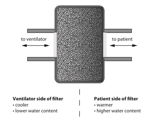
Heat and moisture exchange filter (HMEF)
- HMEF is inexpensive, disposable, passive and efficient enough to provide adequate humidification of dry gases for up to 24 hours.
- It creates a sealed unit, near the patient end of the breathing system, containing a hygroscopic material such as calcium chloride or silica gel.
- As the warm and moist gas from the patient reaches the HMEF, the moisture from the gas condenses onto the hygroscopic surface, simultaneously heating the element via the latent heat of condensation
- With the next inspiration of dry cold gas over the moist element this process is reversed, warming and humidifying the gas the patient receives.
- This process is about 80% efficient
- The addition of a 0.2 mm filter renders the interface impermeable to bacteria and viruses
- The disadvantages are that because it is a passive device, the HMEF is not 100% efficient and the patient will therefore lose heat and moisture over time, although this is negligible. Also, it adds dead space ranging from 8 mL in a paediatric HMEF to 100 mL in an adult, while the additional resistance can be up to 2.0 cm H2O ( may not create issues if respiratory function is not compromised significantly).
- The hygroscopic material and filter can act as a dam to secretions, greatly increasing the work of breathing. This is easily remedied by vigilance and replacement.
Water bath humidifiers
- Active water baths can achieve 100% efficiency and can also be used to heat the patient
- But they are bulky and complex and better suited for patients requiring longer-term ventilation or oxygen therapy.
- Passive water baths simply consist of a chamber of water through which the inspired gas is bubbled to achieve full saturation.
- The disadvantage is that the temperature of the water limits the maximum achievable humidity.
- Cooling of the water bath happens secondary to the latent heat of vaporization as the water is vaporized. This is remedied by an active system incorporating a heating element and thermostat.
- The system is designed to keep the water bath at a specific temperature (40–60°C). This increases the temperature of the gas mixture and therefore the achievable humidity. This system is capable of delivering fully saturated gas at 37°C at high flow rates which represents a significant advantage over the HMEF.
- All water baths need to include a water trap in their design, because the cooling of the gas as it moves away from the hot bath to the patient will result in condensation which can accumulate and could result in wet drowning. This risk may be minimized by heating the tubing and preventing condensation forming.
- Water baths at around 40°C minimize the risk of scalding the patient’s airways with overly heated gas, but run the risk of creating an ideal environment for microbial growth.
- By heating the water to 60°C the risk of bacterial contamination is reduced but the gas temperature must now be very carefully monitored.
- A thermistor on a feedback loop to the water bath’s thermostat can adjust the temperature of the water, and therefore inspired gas, to ensure that the patient does not suffer from airway scalding.
- The ideal size of water droplets for humidification is 5–10 microns. Smaller droplets will descend to the alveoli and larger ones will condense in the trachea.
- Scalding is a risk associated with water bath types when the temperature within exceeds 37C.
- Nebulisers are more efficient than water bath types of humidifiers. The Bernoulli effect describes the drop in pressure occurring at a jet, where velocity is greatest, which is employed to draw up water from a reservoir. This effect is used in spinning disc and gas driven humidifiers among others.
Latent Heat and its applications in anesthesia practice
- Heat capacity: The heat energy required to raise the temperature of a given object by one degree. (J.K−1 or J.°C−1)
- Specific heat capacity: The heat energy required to raise the temperature of one kilogram of a substance by one degree. (J.kg−1.K−1 or J.kg−1.°C−1)
- But not all heat energy results in a temperature change.
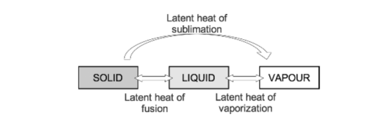
- Latent heat: This is the heat energy that is required for a material to undergo a change of phase. (J) The heat is not utilised for raising the temperature, but for changing the phase.
- If heat is applied to matter, temperature increases until the melting or boiling point is reached. At these points the addition of further heat energy is used to change the state of matter from solid to liquid and from liquid to gas. This does not cause a change in temperature. The energy required at these points is referred to as latent heat of fusion and latent heat of vaporisation, respectively.
- Specific latent heat is the heat required to convert one kilogram of a substance from one phase to another at a given temperature.
- As temperature increases, the amount of additional energy required to overcome the intermolecular forces of attraction falls until the critical temperature of a substance is reached. At this point the specific latent heat is zero, as no further energy is required to complete the change in state of the substance.
APPLICATIONS
- Variable bypass vaporisers function by passing a small amount of fresh gas through the vaporising chamber, which is fully saturated with anaesthetic vapour. This removes vapour from the chamber. Further vaporisation from the anaesthetic liquid must occur to replace the vapour removed, which requires energy from the latent heat of vaporisation. This cools the remaining liquid, reducing the saturated vapour pressure and thus the concentration of anaesthetic vapour delivered, resulting in an unreliable device.
- Temperature compensation features help to overcome this problem; a copper heat sink placed around the vaporising chamber is one such example. Copper has a high heat capacity and donates energy required for latent heat of vaporisation, maintaining a stable temperature and reliable delivery of anaesthetic agent.
- Evaporation of sweat is another example. It requires the latent heat of vaporisation, which is provided by the skin’s surface, exerting a cooling effect upon the body.
- Evaporation from open body cavities can be a cause of significant heat loss from patients while under anaesthesia.
- These principles are also applicable to blood transfusion. Blood is stored at 5°C and has a specific heat capacity of 3.5 kJ·kg−1·K−1. If cold blood were transfused into a patient without pre-warming, the heat energy required to warm the blood to body temperature would need to be supplied by the patient, which would have a significant cooling effect.
Ohm’s Law
- The strength of an electric current varies directly with the electromotive force (voltage) and inversely with the resistance. So I = V/R or V = IR where V is voltage, I is current and R is resistance.
- The equation can be used to calculate any of the above values when the other two are known. When R is calculated, it may represent resistance or impedance depending on the type of circuit being used (AC/DC)
- Resistance: The opposition to flow of direct current. (ohms, Ω)
- Reactance: The opposition to flow of alternating current. (ohms, Ω)
- Impedance: The total of the resistive and reactive components of opposition to electrical flow. (ohms, Ω)
- The reactance of an inductor is high and comes specifically from the back electromotive force that is generated within the coil. It is, therefore, difficult for AC to pass.
- The reactance of a capacitor is relatively low but its resistance can be high; therefore, direct current (DC) does not pass easily.
Thermistors and their use in anesthesia
- A thermistor is a temperature-sensitive resistor whose resistance changes with temperature.
- Most temperature-sensitive resistors are constructed from a semiconductor material (carefully chosen metal oxides) and the resistance increases with a fall in temperature (they have a negative temperature coefficient)
- So they are known as negative thermal conductivity (NTC) thermistors.
- A Wheatstone bridge circuit is used to measure the resistance accurately.
- The main disadvantage of thermistors is the non-linear resistance versus temperature characteristic, although this can be compensated for using an appropriate calibration equation programmed into an electronic measurement system.
- Thermistors remain highly popular due to their cost, miniature size and convenience.
- Thermistor probes are commonly placed in the nasopharynx, oesophagus, rectum or bladder (integrated with a urinary catheter).
- They have excellent accuracy and their small mass means that there is a quick response to variations in temperature.
- But they ‘age’ and their resistance changes with time. They also exhibit hysteresis.
- True or False? ‘A thermistor comprises a junction of dissimilar metals’
- Answer: False. Dissimilar junctional metals are thermocouples
- True or false: ‘A thermistor demonstrates the Seebeck effect’
- Answer: False. The Seebeck effect applies to themocouple
Turbulent flow and it’s clinical applications
- The flow pattern of a river running over rapids is very different to the steadily flowing river (laminar flow). Here, the water’s path of travel becomes far less predictable than for laminar flow. This is an example of turbulent flow. An intermediate example is water flowing near the bank of a steadily flowing river, which often tends to meander, turning round in gentle circles. This is an example of eddies, the forerunner to full-blown turbulence.
- As flow is, by definition, unpredictable, there is no single equation that defines
the rate of turbulent flow as there is with laminar flow. - But, in well controlled circumstances the point at which flow changes from laminar to turbulent flow can be estimated using the Reynolds number, Re, which is named after Osborne Reynolds (1842–1912) of Manchester University, an engineering professor.
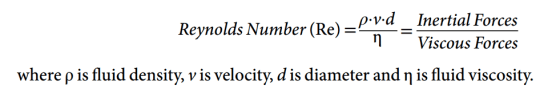
- The Reynolds number allows us to predict whether turbulent or laminar flow would occur in a given system. The Reynolds number is a dimensionless quantity, i.e. it has no units. It is defined as the ratio of inertial and viscous forces. A Reynolds number <2000, where viscous forces predominate, predicts flow to be laminar. Between 2000 and 4000, both laminar and turbulent flow are anticipated. Above 4000, flow is likely to be completely turbulent because inertial forces are dominant. Critical flow is the point above which turbulent flow commences, which occurs at a Reynolds number of around 2000.
- Viscosity is the important property for laminar flow
- Density is the important property for turbulent flow
- Reynold’s number of 2000 delineates laminar from turbulent flow (Tim and Pinnock: Re < 1000 is associated with laminar flow, while Re > 2000
results in turbulent flow) - A high Reynolds number means that the inertial forces dominate, and any eddies in the flow will be easily created and persist for a long time, creating turbulence
- In a given airway with a known gas and flow velocity, the likelihood of turbulent flow can be predicted from Re.
- But the pressure–flow relationship for turbulent flow is different because the pressure gradient producing the flow is:
- >Proportional to (flow velocity)2
>Dependent on gas density and - >independent of viscosity
>Inversely dependent on (radius)5 - APPLICATIONS:
- Both laminar and turbulent flow exist within the respiratory tract, usually in mixed patterns. Turbulence increase the effective resistance of an airway compared with laminar flow. Turbulent flow occurs at the laryngeal opening, the trachea and the large bronchi (generations 1–5) during most of the respiratory cycle. It is usually audible and almost invariably present when high resistance to gas flow is encountered
- The principal sites of resistance to gas flow in the respiratory system are the nose and the major bronchi rather than the small airways. Since the cross-sectional area of the airway increases exponentially as branching occurs, the velocity of the airflow decreases markedly with progression through the airway generations, and laminar flow becomes predominant below the fifth generation of airway
Laminar flow (For clinical applications, see post: Turbulent flow)
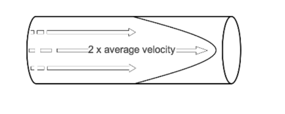
- When watching a steadily flowing river, the flow of water may be seen to be fastest in the middle, while near the banks of the river the water flows more slowly. This behaviour is also observed in fluid travelling slowly along a wide straight cylindrical tube, where the fastest velocity occurring in the centre of the tube and the slowest at the edge where there is friction between the wall of the tube and the fluid. This is known as laminar flow.
- Viewed from the side as it is passing through a tube, the leading edge of a column of fluid undergoing laminar flow appears parabolic. The fluid flowing in the centre of this column moves at twice the average speed of the fluid column as a whole. The fluid flowing near the edge of the tube approaches zero velocity.
- Hagen (in 1839) and Poiseuille, a surgeon (in 1840) discovered the laws governing laminar flow through a tube. If a pressure P is applied across the ends of a tube of length, l, and radius, r. Then the flow rate, Q, produced is proportional to:
*The pressure gradient (P/l) *The fourth power of the tube radius *The reciprocal of fluid viscosity . This is often combined as: 
- where Q is flow, ΔP is pressure gradient, r is radius, η is fluid viscosity and l is length
- Also Q = Pressure Difference/ Resistance; so Resistance= Pressure Difference / Q. When we apply H-P equation into this: Resistance, is dependent on the length of the tube and the viscosity of the fluid, but inversely related to the fourth power of the radius.
- Also note: Viscosity is the important property for laminar flow, whereas density is the important property for turbulent flow. Reynold’s number of 2000 delineates laminar from turbulent flow
VIVA SCENE: PACEMAKERS, AICDs AND THE ANESTHESIOLOGIST
- The need for cardiac pacing results from conduction disorders of the heart, which may or may not be associated with IHD.
- Permanent Pacemakers (PPM) are classified using a five letter code( See below)
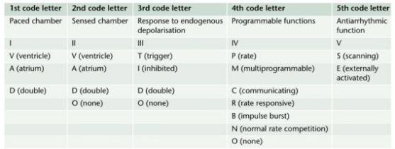
- For example DDDR means atrial and ventricular pacing (I), atrial and ventricular sensing(II) with double/adaptive (III) rate response(IV)
- Most modern units work in DDD mode, and provide atrial pacing in the presence of atrial bradycardia and ventricular pacing after an endogenous/paced atrial depolarization, if a spontaneous ventricular beat is absent
- KEY PERIOPERATIVE QUESTIONS: 1. Indication for pacemaker and associated cardiac comorbidities 2. Type of pacemaker; also how does the rate modulation work in that pacemaker? Chest x-ray will help to find the pulse generator siting and lead placement (atrium/ventricle/both) and number 3. When it was last checked 4. Requirement of diathermy for the procedure 5.Whether anticipating any other factor/s interfering with pacemaker function? 6. Surgical site proximity to the pacemaker 7. What is your plan to avoid inappropriate pacemaker function (e.g. change from demand to fixed rate mode) in case of interference? Cardiology/ Pacemaker programmer support may be needed for the same
- WHAT ECG CAN TELL: 1. If native rhythm predominates–> patient not PPM dependent 2. If all beats preceeded by a pacemaker spike–> pacemaker dependent 3. No evidence of pacemaker activity–> magnet might be applied over the pulse generator to switch to fixed rate pacing. If pacemaker is activated by a magnet to pace at a fixed rate, spike may fall in the refractory period and fail to stimulate the ventricle 4. If pacemaker spike is not followed by p or QRS waves –> PPM malfunction
- The characteristics of a PPM can be changed externally by application of a magnet or using radiofrequency generators, usually for a change of demand to fixed rate. Application of a magnet over a non-programmable VVI pacemaker will convert it to VVO asynchronous mode. The modern reprogrammable units need a cautious approach to the use of magnets. In this case, there is a risk of reprogramming ( with inappropriate settings), but it will remain in the asynchronous fixed rate mode, until the magnet is removed, after which the ‘inappropriate’ reprogrammed mode may take over
- ABOUT THE RATE RESPONSE FUNCTION: Such PPMs may sense electrical activity or vibration (e.g. shivering) and cause a tachycardia in response. Some measure respiratory rate by sensing thoracic impedence and adjust HR accordingly. Some sense blood temperature and so may cause a tachycardia when warming a hypothermic patient. With hypokalemia, there is a risk of loss of pacing capture and with hyperkalemia, there is risk of VT or VF.
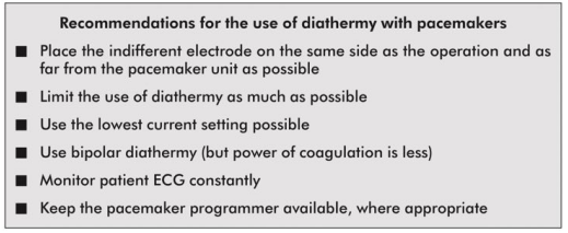
- INTRAOPERATIVE STEPS: 1. If possible, avoid surgical diathermy; but if unavoidable, bipolar is safer than unipolar diathermy. 2. Monopolar where necessary, should be used in short bursts with at as low energy levels as possible 3. Diathermy plate should be kept on the same side, as far away from the PPM as possible 4. Cables from diathermy equipment also should be kept away from the PPM 5. Confirm device functionality on completion of the surgery
- Surgical diathermy can cause 1. Ventricular fibrillation 2. ‘Reprogramming’ of programmable PPMs 3. Inhibition of demand function 4. Unit failure 5. Asystole
- AUTOMATIC IMPLANTABLE CARDIOVERTER DEFIBRILLATORS (AICDs) AND THE ANESTHESIOLOGIST: They consist of a set of lead electrode systems for sensing-pacing-delivery of shocks for cardioversion/ defibrillation; modern units can also function as DDD pacemakers. In general, AICDs better be deactivated with a programming device before surgery to avoid inappropriate shock delivery due to electrical interference; in modern AICDs, the anti-bradycardia function can be left activated (Consult the manufacturer for this). The effect of magnets are inconsistent across devices; but modern units are inhibited by magnets. If required, external pads can be placed over the patient with external defibrillators ready to attach, for use in case any tachyarrhythmias occur during this period. Take all precautions as in the case of PPM. Postoperatively, the ICD should be checked and reactivated.
VIVA SCENE: DIATHERMY AND THE ANESTHESIOLOGIST
- WHY WE SHOULD KNOW? 1.Anesthesiologist may be blamed if burns occurs due to malposition of the plate 2. It can interfere with monitors e.g. ECG and pulseoximeters 3. It can disrupt pacemaker function in a patient, having it.
- Diathermy depends on the heat generated when a current pass through a tissue and is used to coagulate blood vessels and cut through tissues
- A high frequency current is necessary for this, as myocardium is sensitive to DC and low frequency AC [the usual mains frequency of 50 Hz] will precipitate VF. Very high frequencies have minimal tissue penetration and pass without harming the myocardium
- A 0.5 MHz alternating sinewave is used for cutting and a 1.0-1.5 MHz pulsed/ damped sinewave pattern is used for coagulation
- UNIPOLAR DIATHERMY & PROBLEMS: Here the forceps represent one electrode (small area, high current density and significant heat generation) and the diathermy plate ( indifferent electrode) over the patient represent the other electrode (large area, less heat). If the the plate is malpositioned, the current may pass through any point of metal contact *like ECG electrodes, metal poles of lithotomy, operation table etc, and may result in passage of high current density as the area of contact is small, resulting in a burn. So we should ensure that the plate is in close and proper contact with a large, highly perfused (will dissipate heat) area of skin (adhesive gels are useful). If we place it near to metal prosthesis (e.g. Hip), which has a low resistance than tissue, it will generate a high current density, resulting in burns. A unipolar diathermy can generate 150-400 Watts of energy.
- BIPOLAR DIATHERMY: Current passes between the two blades of the forceps; so requires no plate; safer in patients with pacemaker. But can generate only 40 Watts of energy. So efficacy is less and may be used for coagulation of small blood vessels
- OTHER PROBLEMS: Sometimes diathermies may cause ignition of skin preparation spirit. Newer diathermies dont have earthing; but if your machine is having earthing, an inappropriate earthing will result in current passing through other routes mentioned above*, resulting in burns.
- Cautious use of diathermy is required in patients with pacemakers:
VOCAL CORD PALSIES
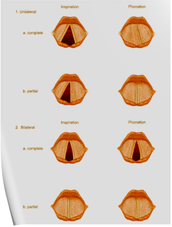
Under normal circumstances, the vocal cords meet in the midline during phonation. On inspiration, they move away from each other. They return toward the midline on expiration, leaving a small opening between them. When laryngeal spasm occurs, both true and false vocal cords lie tightly in the midline opposite each other.
The recurrent laryngeal nerve (RLN) carries both abductor and adductor fibers to the vocal cords.
Selmon’s law: The abductor fibers are more vulnerable, and moderate trauma causes a pure abductor paralysis. Severe trauma causes both abductor and adductor fibers to be affected. N.B.:- Pure adductor paralysis does not occur as a clinical entity.
Scenario 1- PURE UNILATERAL ABDUCTOR PALSY: As adduction is still possible on the affected side, the opposite cord come and meet in the midline on phonation. However, only the normal cord abducts during inspiration.
Scenario 2- COMPLETE UNILATERAL PALSY OF THE RLN: Both abductors and adductors are affected. On phonation, the unaffected cord crosses the midline to meet its paralyzed counterpart, appearing to lie in front of the affected cord. On inspiration, the unaffected cord moves to full abduction.
Scenario 3- BILATERAL INCOMPLETE ABDUCTOR PALSY: When there is incomplete bilateral damage to the recurrent laryngeal nerve, the adductor fibers draw the cords toward each other, and the glottic opening is reduced to a slit, resulting in severe respiratory distress.
Scenario 4- COMPLETE BILATERAL PALSY OF THE RLN: With a complete palsy, each vocal cord lies midway between abduction and adduction, and a reasonable glottic opening exists.
Thus, bilateral incomplete palsy is more dangerous than the complete variety.
Scenario 5- DAMAGE TO SUPERIOR LARYNGEAL NERVE/S: Damage to the external branch of the superior laryngeal nerve or to the superior laryngeal nerve trunk causes paralysis of the cricothyroid muscle (the tuning fork of the larynx), resulting in hoarseness that improves with time because of increased compensatory action of the opposite muscle. The glottic chink appears oblique during phonation. The aryepiglottic fold on the affected side appears shortened, and the one on the normal side is lengthened. The cords may appear wavy. The symptoms include frequent throat clearing and difficulty in raising the vocal pitch.
Scenario 6- TOTAL BILATERAL PARALYSIS OF VAGUS NERVES: This affects the recurrent laryngeal nerves and the superior laryngeal nerves. In this condition, the cords assume the abducted, cadaveric position. The vocal cords are relaxed and appear wavy. A similar picture may be seen after the use of muscle relaxants.
N.B:- Topical anesthesia of the larynx may affect the fibers of the external branch of the superior laryngeal nerve and paralyze the cricothyroid muscle, signified by a “gruff” voice. Similarly, a superior laryngeal nerve block may affect the cricothyroid muscle in the same manner as surgical trauma does.
Reference: Benumof and Hagberg’s Airway Management, Third edition
