VIVA SCENE: HYPOCALCAEMIA

Plasma calcium < 2.2 mmol/L

Normal values: Total calcium 2.25-2.60 mmol/L; ionised calcium 1.12-1.32 mmol/L

HYPOCALCAEMIA CAUSES:

  • Decreased parathyroid hormone

  • Decreased Vitamin D activity (e.g. intestinal malabsorption, liver disease, CRF)

  • Increased calcium loss (e.g. chelating agents, calcification of soft tissues)

  • Decreased ionised calcium (e.g. alkalosis)

  • Tumour Lysis Syndrome
  • Diarrhoea, vomiting, and nasogastric suction can cause hypomagnesaemia with secondary hypocalcaemia (HSH)

CLINICAL FEATURES:

  • Tetany
  • Seizures
  • Emotional instability/agitation/anxiety
  • Myopathy

ECG:

  • QTc prolongation by prolonging the ST segment

  • Torsades de pointes and atrial fibrillation in severe cases

NB: The corrected QT interval (QTc) is taken as the time between the beginning of the QRS complex and the end of the T wave, it is less than 440 ms in men and 460 ms in women. Severe hypocalcaemia (less than 1.9 mmol/L) may cause a prolongation of the QTc. A QTc greater than 500 ms is associated with an increased risk of Torsades de Pointes.

TREATMENT:

  • Ca2+ 0.5mL/kg (max 20mL) of 10% calcium gluconate OR 0.2mL/kg of 10% calcium chloride
  • Administer by slow IV (max 2 mL/min), repeat if necessary.
  • Calcium can precipitate or exacerbate digitalis toxicity therefore IV calcium must be given very slowly in patients on digoxin and the ECG must be monitored continuously
VIVA SCENE: DESFLURANE

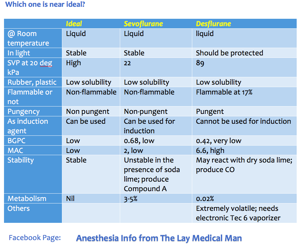
  • Desflurane is a fluorinated methyl ethyl ether (MW = 168)
  • Its an irritant gas, so cannot be used for induction
  • MAC is 6.6% ( for an infant the MAC raises to 9.4%)
  • Boiling point is low at 22.8 degrees compared to other agents
  • SVP at 20 degrees is very high at 89.2 compared to other agents
  • Extremely volatile; so needs an electronic Tec 6 vaporizer
  • Has a low OGPC of 29 = potency is low
  • Has a high BGPC of 0.42 = rapid onset and offset
  • Only 0.02% of desflurane will get metabolised (to trifluoroacetic acid)
  • Its effect on the CVS is modest: reduce SVR only above 2.2 MAC and effect on contractility is less than other agents. It increases HR like isoflurane
  • Like other agents it reduces TV and increases RR
  • Like other agents, it has the potential to increase cerebral blood flow above 1 MAC
  • With dry sodalime, it has the potential to react and produce carbon monoxide

VIVA SCENE: RADIAL NERVE COURSE AND CAUSES OF INJURY

COURSE:

  • The radial nerve (C5–8, T1) transmits fibres from all the roots of the brachial plexus.
  • At its origin it lies behind the third part of the axillary artery; it then passes between the long and medial heads of triceps into the posterior compartment of the arm, accompanied by the profunda branches of the brachial vessels.
  • It descends first along the spiral groove of humerus, and then between muscle planes
  • A hand’s breadth above the elbow, the nerve reaches the lateral margin of the humerus, and enters once more into the anterior compartment of the arm, where it lies between brachialis and brachioradialis. At this point, the nerve is susceptible to compression injury, in particular from an arterial tourniquet placed too low around the arm.
  • It ends in front of the lateral epicondyle of the humerus by dividing into two terminal branches, the superficial radial nerve and the posterior interosseous nerve.

BRANCHES:

The muscular branches:

  • Medial group (arising in the axilla): Supplies: a long head of triceps b medial head of triceps.
  • Posterior group (arising in the spiral groove) : a medial head of triceps b lateral head of triceps c anconeus.
  • Lateral group: a brachialis (together with musculocutaneous nerve) b brachioradialis c extensor carpi radialis longus

The cutaneous branches:

  • The posterior cutaneous nerve of the arm, which arises in the axilla and supplies the skin over the proximal one-third of the posterior aspect of the arm.
  • The posterior cutaneous nerve of the forearm, which arises in the spiral groove,  supplies the skin over the posterolateral aspect of the forearm.
  • The lower lateral cutaneous nerve of the arm, supplies an area of skin over the lateral aspect of the arm just above the elbow.

The posterior interosseous nerve (terminal branch), passes into the posterior compartment of the forearm. It supplies supinator, many extensors and abductor pollicis longus. It also supplies the wrist joint.

The superficial radial nerve (terminal branch) is entirely sensory. It divides into dorsal digital nerves and supply the dorsal aspect of the hand upto the radial half of the ring finger.

CAUSES OF RADIAL NERVE INJURY:

  • Saturday Night Palsy: Caused by prolonged compression of the nerve at the spiral groove.
  • Mechanical compression of the radial nerve in the spiral groove can also occur as a result of the continuous use of crutches or prolonged kneeling in a “shooting” position
  • As a delayed complication of a chronic intramuscular injection leading to muscle fibrosis
  • From prolonged inflation of an automatic blood pressure cuff especially when placed over the distal third around the arm, in a lean patient. Here, the radial nerve lies in direct contact with the humerus and there are no muscle fibers to act as a cushion between the nerve and the periosteum of the bone
  • Humeral shaft fracture

VIVA SCENE: PAIN: Most important points summarised

DEFINITION:

  • Pain is ‘an unpleasant sensory and emotional experience associated with actual or potential tissue damage’. (IASP: International Association for the Study of Pain)

CLASSIFICATION:

According to chronicity

  • Acute: Recent onset pain with identifiable cause
  • Chronic: Pain persisting beyond the time of injury or healing without definable cause

According to nature

Nociceptive pain: Pain occurring due to stimulation of peripheral sensory nerve fibres (nociceptors) that respond to potentially harmful stimuli; further divided into

  • Superficial and Deep somatic pain: Relatively well localized pain due to activation of peripheral nociceptors.
  • Visceral pain (organs, viscera) – Diffuse pain that may be difficult to localize or referred to a superficial structure which is usually distant to the source of the pain

Neuropathic pain: Pain that occurs due to a primary lesion or dysfunction in the nervous system itself.

THE GATE CONTROL THEORY OF PAIN:

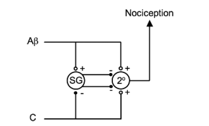
  • Melzack and Wall theorized that the transmission of a peripheral painful stimulus to the CNS occurs via a gate at spinal cord level. This gate comprises an inhibitory interneurone in the substantia gelatinosa that may be either stimulated or inhibited by different afferent inputs.
  • Screen Shot 2019-09-06 at 1.02.03 pm
  • The Aβ fibres are examples of afferents that stimulate inhibitory interneurones (in the substantia gelatinosa (SG)) and, therefore, prevent nociceptive transmission to the CNS. The C fibres are examples of afferents that inhibit inhibitory interneurones and, therefore, enhance nociceptive transmission. Note that both types of fibres stimulate the second-order neurone (2°) directly but it is the interneurone that modifies the transmission.

  • Laminae 2 & 3 are called the substantia gelatinosa and is the site of the ‘gate control theory’ of pain.

PAIN PATHWAY

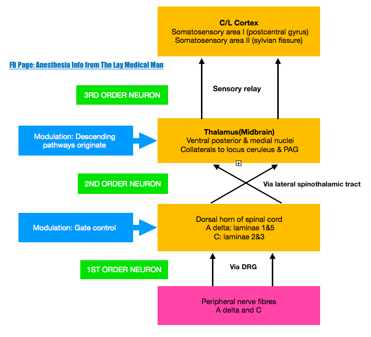
  • There are three levels of neuronal involvement and the signals may be modulated at two points during their course to the cerebral cortex. Descending inhibitory pathways arise in the midbrain and pass to the dorsal horn. Multiple different neurotransmitters are involved in the pathway and include GABA,NMDA, noradrenaline and opioids.

  • Noxious stimuli –>tissue damage –>mediators–> nociceptors stimulation–> action potential –> propagated along afferent nerve fibres C & Aδ –> dorsal horn of the spinal cord –> Synaptic transmission with secondary interneurones occurs in Rexed’s laminae –> secondary interneurones decussate and travel in the anterolateral spinothalamic tracts –> through the brainstem –>to the thalamus –> tertiary afferents project to the somatosensory cortex.

  • Some spinal ascending fibres transmit impulses to the reticular-activating system, and to higher centres involved with affect, emotion and memory.

  • Descending fibres from cortex, thalamus and brainstem exert an inhibitory influence on pain transmission in the dorsal horn

  • An immediate polysynaptic withdrawal reflex occurs at the level of the spinal cord as some interneurones connect to motor neurones at many levels. This is a protective reflex.

  • Screen Shot 2019-09-06 at 1.42.15 pm

DESCENDING INHIBITORY PATHWAYS

  • Periaqueductal grey (PAG) in the midbrain receives projections from the thalamus, hypothalamus, amygdala and cortex, and delivers projections to the nucleus raphe magnus (NRM) in the medulla, whose fibres synapse in the substantia gelatinosa of the dorsal horn. Its transmitters include endorphins and enkephalins (MOP opioid receptors) and serotonin (5HT1 and 5HT3 receptors).

  • Locus caeruleus (LC) is an important brainstem nucleus projecting descending inhibitory pathways to the dorsal horn via noradrenaline (α-adrenergic receptors).

VIVA SCENE: PARACETAMOL Vs MORPHINE CENTRAL MOA

PARACETAMOL:

Central action via COX 3 inhibition which is associated with decreased brain PGE2 levels. It also modulates endogenous cannabinoid system

MORPHINE:

Morphine work by stimulating presynaptic Gi-protein-coupled MOP and KOP opioid receptors. Binding of the ligand causes the following events:

> Closure of voltage-gated Ca2+ channels

> Decreased cAMP production

> Stimulation of K+ efflux from the cell

> Hyperpolarisation of the cell membrane.

> This leads to decreased excitability of the cell and therefore decreased neurotransmitter release and pain transmission

VIVA SCENE: Ideal Inhalational Agent

Screen Shot 2019-09-05 at 7.20.43 pm

VIVA SCENE: THROMBOELASTOGRAPHY (TEG) AND OTHER QUESTIONS

TEG is a relatively new modality for monitoring coagulation which is very useful during management of trauma and also in the perioperative scenario..

BASIS:

  • The 2 main components of the TEG machine are a cup and a pin. Whole blood is mixed with the activating agent kaolin as well as calcium. The cup then oscillates around the pin slowly, at a rate of 6 times per minute, to mimic natural blood flow in vivo and activate the clotting cascade. As the clot forms, the torque between the cup and pin is transduced and measured, creating a curve. As the clot breaks down and torque decreases, the tracing converges to represent this. 
  • The different parameters of the curve are then measured to assess current coagulation status.
  • Of the 4 types of TEG assays available, the most common is the rapid TEG. The use of an activator in rapid TEG standardizes the TEG test and speeds up the rate at which clotting takes place, thus making results available more quickly.

INTERPRETATION

Screen Shot 2019-09-04 at 3.20.39 pm

Screen Shot 2019-09-04 at 3.04.41 pm

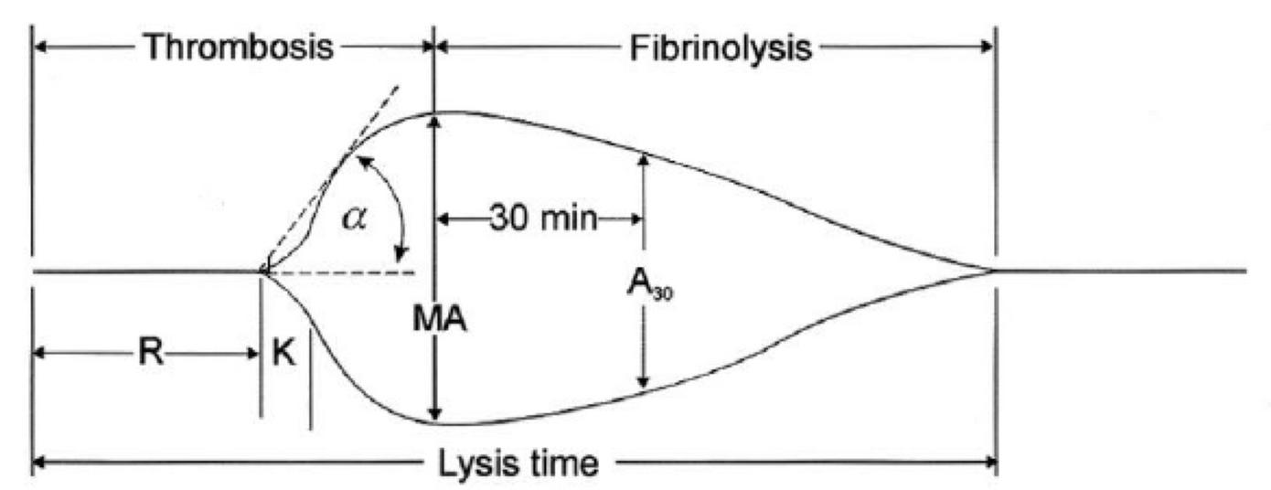
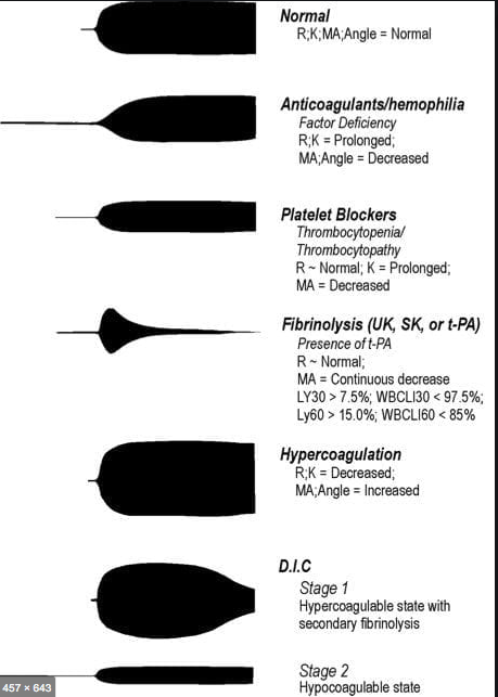
  • R(sec): The first measurement of note is the reaction time (R time). This is the time interval from the start of the test to the initial detection of the clot. Normal R values range between 7.5 and 15 minutes. A prolonged R time may indicate hemodilution or clotting factor deficiencies. The treatment for prolonged R time is to administer FFP as it contains all factors of the coagulation cascade, without further coagulant hemodilution A shortening of R time (< 3 minutes) occurs in hypercoagulable states. Examples would be patients with early disseminated intravascular coagulation (DIC) or septicemia. In these situations, free thrombin is released into the circulating blood, triggering the clotting mechanisms but the patient later begins to bleed because of exhaustion of clotting factors.

  • K (sec) and Angle α (°): The clot strength is measured by these 2 variables in TEG. The K value measures the interval between the R time and the time when the clot reaches 20 mm. Normal K values range between 3 and 6 minutes. Prolongation of the K value with normal platelet count  indicates inadequate amounts of fibrinogen to form fibrin. The treatment for prolonged K value is therefore to administer fibrinogen/cryoprecipitate. The α angle measures a line tangent to the slope of the curve during clot formation.The alpha angle represents the thrombin burst and conversion of fibrinogen to fibrin. Normal α value is between 45° and 55°. A longer K value causes a shallow or more acute angle (<45°), while a shorter K value causes a steeper α angle (>45 °). An angle α <45° suggests a less vigorous association of fibrin with platelets. In this case, treatment begins much higher on the coagulation cascade, with the replacement of both fibrinogen and factor VIII. Thus, these patients can be treated with the administration of cryoprecipitate. Shortening of the K-value indicates a very quick formation of clot, potentially due to hypercoagulability or inappropriate consumption of coagulation factors. A shortened K value also corresponds to a steeper α (>45°). The treatment for shortened K and steeper α is anticoagulation therapy

  • MA (mm): Maximum amplitude is a measurement of maximum clot strength and provides information on both fibrinogen and platelet function. As the clot develops and increases in tensile strength due to platelet activation and binding to fibrin, the tracing increases it’s MA or appears to widen. Normal values are between 50–60 mm. 80% of the MA is derived from platelet function whereas the remaining 20% is derived from fibrin. A low MA value is indicative of low clot strength, which can be caused by decreased fibrinogen levels, low platelet counts, or decreased platelet function. (i) Paired with a prolongation of K value, this could be a sign of the need for cryoprecipitate. (ii) Administration of platelets may be avoided when a low platelet count is combined with a normal MA value (=platelet function is normal) (iii) Treatment with platelets may be indicated for patients with a low MA value (=low platelet function) and normal platelet count. (iv) High MA will occur in the setting of hyperactivity of platelets, and MA above 75 mm indicates a prothrombotic state. In this case, treating with an anticoagulant would be helpful
  • Shear Elastic Modulus Strength, G value or G: is a measure of clot strength or clot firmness, and is calculated based on the amplitude value (A) until the maximum amplitude (MA) is reached. It is the single most important value of the entire assay because it represents the overall function or effectiveness of the clot. Normal G values are between 5.3 and 12.4 dynes/cm2. A G value >10 dynes/cm2 indicates increased risk of thrombosis. Treatment for high G is accomplished by the use of platelet inhibitors such as Clopidogrel or Aspirin. Aspirin is usually not preferred because it inhibits platelet adherence rather than platelet aggregation. A G <5 dynes/cm2 places a patient at increased risk of hemorrhage
  • As time progresses during the TEG assay, the tracing will remain at maximal amplitude for a period of time, after which clot lysis begins. Normally, lysis continues for a period of up to 15 minutes. A computerized algorithm automatically estimates the percentage of lysis occurring over time. This is called the Estimated Percentage of Lysis or EPL. After 30 minutes, EPL becomes EPL30 or succinctly LY30 (i.e. percentage of lysis at 30 minutes). Both the EPL and LY30 are measurements of excessive fibrinolysis since they measure the percentage decrease in amplitude after MA. An EPL between 7.5 and 15%, when accompanied by a very high G, reflects a hyperfibrinolytic and hypercoagulable state typical of patients with early DIC. A very high EPL or LY30 (>20%) may indicate the need for antifibrinolytic therapy, such as the use of transexamic acid or aminocaproic acid. LY30 is also useful for patients undergoing thrombolytic drug therapy. This can be observed by rapid curve convergence.

Ref: Thromboelastography: Clinical Application, Interpretation, and Transfusion Management, Shawn Collins et al AANA Journal Course, 2016

HOW DO WE TEST CLOTTING?

  • By doing tests like aPTT, PT & INR, Platelet Count, ACT, Bleeding Time, fibrinogen and factor levels, TEG etc
  • The aPTT and INR use different reagents to measure the time to form a clot in vitro after platelet-poor plasma from blood collected in a calcium chelating tube, is recalcified
  • The aPTT is prolonged with the deficiency of factors of the intrinsic pathway: Fs 8,9,11,12. Also the factors involved in the common pathway (Fs 1,2,10)e.g. Heparin therapy, DIC, liver disease
  • The INR is prolonged especially with deficiency of F 7; but also with deficiency of Fs 1,2,5,10 e.g.  warfarin therapy, vitamin K deficiency, DIC, liver disease
  • N.B Warfarin inhibits the gamma carboxylation of vitamin K dependent factors 2,7,9,10
  • BLEEDING TIME :Duke’s method: Sterilize the finger tip using rectified spirit and allow to dry. Make a sufficiently deep prick using a sterile lancet, so that blood comes out freely without squeezing. Note the time (start the stop-watch) when bleeding starts. Mop the blood by touching the finger tip with a filter paper. This is repeated every 15 seconds, each time using a fresh portion of the filter paper, till bleeding stops. Note the time (stop the stop-watch). Normal value is upto 4 minutes. 
  • CLOTTING TIME: Capillary tube method: (Wright’s method). Under sterile precautions make a sufficiently deep prick in the finger tip. Note the time when bleeding starts (start the stop watch). Touch the blood drop at the finger tip using one end of the capillary tube kept tilted downwards. The tube gets easily filled by capillary action. After about two minutes start snapping off small lengths of the tube, at intervals of 15 seconds, each time noting whether the fibrin thread is formed between the snapped ends. Note the time (stop the stop watch) when the fibrin thread is first seen. Clotting time is the interval between the moment when bleeding starts and the moment when the fibrin thread is first seen.

    Normal value is 3 to 10 minutes.

  • Bleeding time depends on the integrity of platelets and vessel walls, whereas clotting time depends on the availability of coagulation factors

VIVA SCENE: CARBON MONOXIDE (CO) POISONING

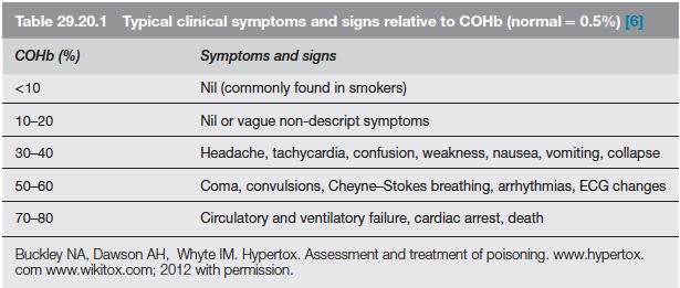
AETIOLOGY: Carbon monoxide is produced by incomplete combustion and is found in car exhaust, faulty heaters, fires and in industrial settings. Carboxyhaemoglobin (COHb) concentrations in cigarette smokers range as high as 10%.

MECHANISM: Binds to Hb with 210 times affinity than O2: so reduce the O2 carrying capacity of blood. Also disrupts oxidative metabolism, binds to myoglobin and cytochrome oxidases, causes lipid peroxidation. Final result is tissue hypoxia. Severity depends on the duration of exposure, CO levels and patients pre-event health status: pre-existing cerebral disease, cardiac failure, hypovolemia and anemia increase toxicity

DIFFERENTIAL DIAGNOSIS: Cyanide poisoning ( suspected when CNS effects are out of proportion with COHb concentrations and if there is a marked lactic acidosis)

Screen Shot 2019-09-04 at 11.31.29 am

EVALUATION & MANAGEMENT:

  • ABC approach
  • Secure the airway; if GCS<8, consider intubation
  • Stabilize respiration:  consider mechanical ventilation or CPAP
  • Get intravenous access
  • Send samples for estimation of Hb(?anemia), electrolytes (dyselectrolytemias worsen the cardiac toxicity), COHb levels (to confirm diagnosis; useless in prognosis), blood sugar, ABG and cardiac enzymes. Take an ECG.
  • Metabolic acidosis due to lactate give a clue to the extend of ischemia. Net effect of metabolic acidosis may be beneficial on O2 delivery; but treated if pH<7
  • Patient discouraged from activity
  • 100% O2 reduces the half life of COHb from 4 hours (in ambient air) to 40 minutes. 4 to 6 h of 100% normobaric oxygen will remove over 90% of the carbon monoxide. Oxygen toxicity is unlikely with less than 24 h treatment
  • When immediately available, hyperbaric oxygen (HBO) should be considered with serious CO poisoning. Oxygen at 2–3 atmospheres will further reduce the half-life of COHb to about 20 min but, more importantly, it causes very rapid reversal of tissue hypoxia due to oxygenation of tissue from oxygen dissolved in the plasma. Some clinicians implement it based on the presence of any of the following: history of loss of consciousness, abnormal neuropsychiatric testing or neurological signs, pregnancy. COMPLICATIONS OF HBO: decompression sickness, rupture of tympanic membranes, damaged sinuses, oxygen toxicity

  • CO PRODUCTION WITH SODALIME USE: Occurs when inhalational agents with CHF2 moiety such as desflurane, enflurane, and isoflurane are used with desiccated soda lime granules that was left unused for a long time. Can be significant in smokers especially when very low flows are used. Factors increasing the production of CO include° Type of inhaled anaesthetic agent (magnitude of CO production from greatest to least is desflurane > enflurane > isoflurane > sevoflurane)° High absorbent dryness ° Type of absorbent (at a given water content, baralyme produces more CO than soda lime)° Increased temperature° Higher anaesthetic concentration

VIVA AID: MAO INHIBITORS AND OPIOIDS


  • Some opioid analgesics are associated with a risk of serotonin syndrome in combination with MAOIs due to their serotonergic properties. Other combinations may result in opioid toxicity due to CYP450 enzyme inhibition by the MAOI.
  • Given the widespread availability of several suitable alternative drugs, the combination of dextromethorphan, methadone, pethidine, tramadol, fentanyl or tapentadol with an MAOI should usually be avoided, including in the 14 day period following the withdrawal of an irreversible MAOI.
  • Morphine, codeine, oxycodone and buprenorphine are alternative opioids for patients receiving MAOIs, though starting at a low dose and titrating cautiously against clinical response is advised. Blood pressure and the signs and symptoms of CNS and respiratory depression should be monitored closely.
  • The MAOI/pethidine interaction has two distinct forms: an excitatory and a depressive form. Pethidine must never be used in the presence of MAOIs because of the risk of a fatal excitatory interaction. Morphine does not cause this excitatory interaction, and is the drug of choice provided an allowance is made for possible potentiation of the depressive narcotic effect.


VIVA SCENE: C-SPINE X-RAY

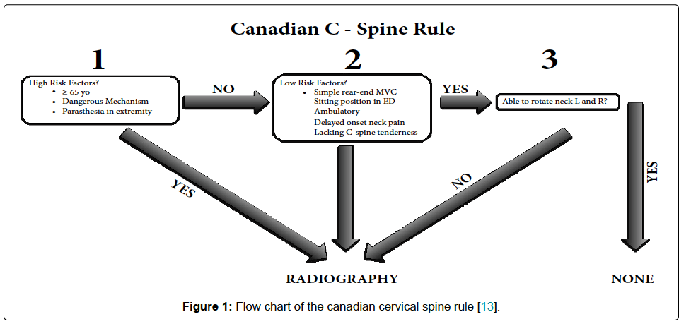
WHETHER TO DO C SPINE IMAGING IN TBI; CRITERIAS:

1. Screen Shot 2019-08-11 at 9.23.39 pm

2. Under the NEXUS guidelines, when an acute blunt force injury is present, a cervical spine is deemed to not need radiological imaging if all the following criteria are met:

  • There is no posterior midline cervical tenderness
  • There is no evidence of intoxication
  • The patient is alert and oriented to person, place, time, and event
  • There is no focal neurological deficit (see focal neurological signs)
  • There are no painful distracting injuries (e.g., long bone fracture)

Screen Shot 2019-08-26 at 11.12.53 am

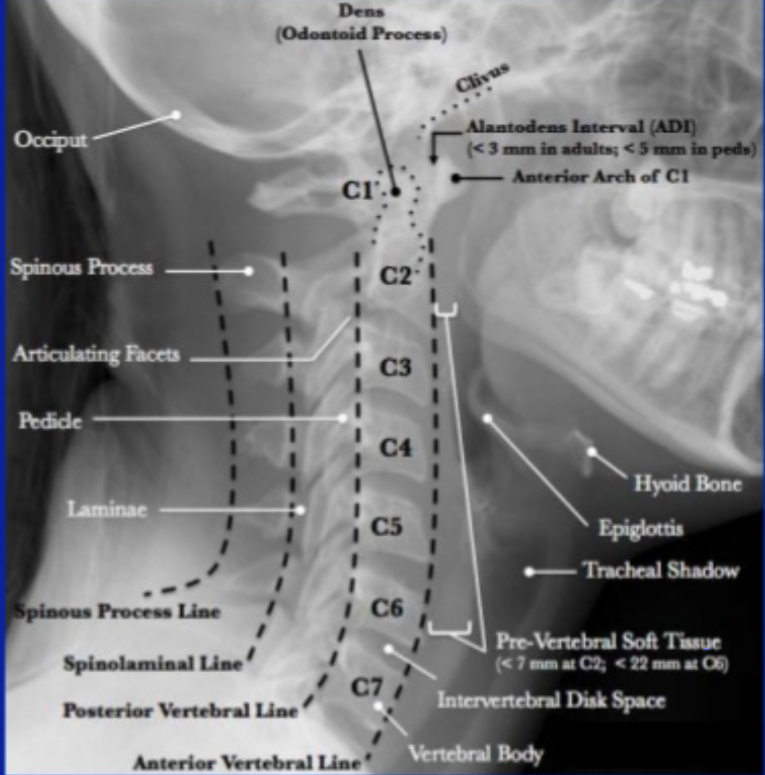
Lateral C-Spine Radiograph. (AABCDs)

A—Adequacy: An adequate film should include all seven cervical vertebrae and C7/T1 junction with optimum density so that the soft tissue shadow is visible clearly.

A—Alignment

a. Atlanto occipital alignment: The anterior and posterior margins of the foramen magnum should line up with the dens and the C1 spinolaminar line.

b. Vertebral alignment

Look for the following four lines (any incongruity= should be considered as evidence of ligamentous injury or occult fracture)

1. Anterior vertebral line—joining the anterior margin of vertebral bodies

2. Posterior vertebral line—joining the posterior margin of vertebral bodies

3. Spinolaminar line—joining the posterior margin of spinal canal

4. Spinous process/ Interspinous line—joining the tips of the spinous processes

B Bony Landmark: vertebral bodies, pedicles, laminae, and the facet joints are inspected

C Cartilagenous space: Predental space or the Atlanto-Dental Interval (ADI): which is the distance from dens to the body of C1. ADI should be < 3 mm in adults and < 5 mm in children. An increase in ADI depicts a fracture of the odontoid process or disruption of the transverse ligament

D—Disc space

Disc spaces should be roughly equal in height and symmetrical.

Loss of disc height can happen in degenerative diseases.

S—soft tissue

Prevertebral soft tissue space thickness can help in the diagnosis of retropharyngeal haemorrhage, which can be secondary to vertebral fractures. Maximum allowable distances :

Nasopharyngeal space (C1): 10 mm

Retropharyngeal space (C2–C4): 5–7 mm

Retrotracheal space (C5–C7): 14 mm in children and 22 mm in adults